Uploaded image for project: 'OASIS Open Document Format for Office Applications (OpenDocument) TC'
  1. OASIS Open Document Format for Office Applications (OpenDocument) TC
  2. OFFICE-2949

10.3.12 <draw:measure> "has arrows at its endpoints"?

    XMLWordPrintable

    Details

    • Resolution:
      Hide

      10.3.12 <draw:measure>

      The <draw:measure> element represents a shape that is used to measure distances in drawings.

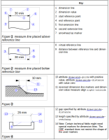
      A measure shape consists of two parallel lines, called extension lines, and a line perpendicular to the extension lines, called a dimension line. The dimension line is displayed between the extension lines and terminated by them. The dimension line has markers at its endpoints. A marker at the start of the dimension line is defined by the draw:marker-start attribute and at the end of the dimension line by the draw:marker-end attribute of the graphic style, which is applied to the measure shape. Where space is limited, reversed markers at the opposite side of the extension line may be used.

      The positions of extension lines and the dimension line are determined by two reference points, called start and end reference points. The start reference point is defined by the attributes svg:x1 and svg:y1. The end reference point is defined by the attributes svg:x2, and svg:y2.

      A dimension value specified by child elements <text:measure> of the <text> child element of the <draw:measure> element may be bound to the length of the dimension line by producers. The position of the dimension value relative to the dimension line is specified by the attributes draw:measure-align and draw:measure-vertical-align.

      The draw:line-distance style attribute defines the distance between the (virtual) line between the reference points, called reference line, and the dimension line. The draw:placing style attributes defines if the measure shape is placed above or below the reference line.

      The first extension line is drawn on a line as defined by the vector from the start reference point to the start point of the dimension line. The extension line will start along this vector at a distance from the start reference point that is defined by the draw:guide-distance style attribute minus the value of draw:start-guide style attribute.

      The second extension line is drawn on a line as defined by the vector from the end reference point to the end point of the dimension line. The extension line will start along this vector at the distance from the end reference point that is defined by the draw:guide-distance style attribute minus the value of draw:end-guide style attribute.

      The end points of the extension lines are at the distance defined by the draw:guide-overhang style attribute after the intersection with the dimension line.

      Editorial note: See attachment for Figures 1-4 and associated Keys.

      Show
      10.3.12 <draw:measure> The <draw:measure> element represents a shape that is used to measure distances in drawings. A measure shape consists of two parallel lines, called extension lines , and a line perpendicular to the extension lines, called a dimension line . The dimension line is displayed between the extension lines and terminated by them. The dimension line has markers at its endpoints. A marker at the start of the dimension line is defined by the draw:marker-start attribute and at the end of the dimension line by the draw:marker-end attribute of the graphic style, which is applied to the measure shape. Where space is limited, reversed markers at the opposite side of the extension line may be used. The positions of extension lines and the dimension line are determined by two reference points, called start and end reference points . The start reference point is defined by the attributes svg:x1 and svg:y1. The end reference point is defined by the attributes svg:x2, and svg:y2. A dimension value specified by child elements <text:measure> of the <text > child element of the <draw:measure> element may be bound to the length of the dimension line by producers. The position of the dimension value relative to the dimension line is specified by the attributes draw:measure-align and draw:measure-vertical-align. The draw:line-distance style attribute defines the distance between the (virtual) line between the reference points, called reference line , and the dimension line. The draw:placing style attributes defines if the measure shape is placed above or below the reference line. The first extension line is drawn on a line as defined by the vector from the start reference point to the start point of the dimension line. The extension line will start along this vector at a distance from the start reference point that is defined by the draw:guide-distance style attribute minus the value of draw:start-guide style attribute. The second extension line is drawn on a line as defined by the vector from the end reference point to the end point of the dimension line. The extension line will start along this vector at the distance from the end reference point that is defined by the draw:guide-distance style attribute minus the value of draw:end-guide style attribute. The end points of the extension lines are at the distance defined by the draw:guide-overhang style attribute after the intersection with the dimension line. Editorial note : See attachment for Figures 1-4 and associated Keys.

      Description

      Not unclear that "arrows" are required by vague about what sorts of arrows.

      For ODF-Next we need to define default graphic shapes for arrows and a host of other graphic shapes that we mention but don't define.

      Not possible for ODF 1.2 given the constraints about not breaking with ODF 1.0/1.1 with more definite requirements.

        Attachments

          Activity

            People

            • Assignee:
              Unassigned
              Reporter:
              patrick Patrick Durusau
            • Watchers:
              2 Start watching this issue

              Dates

              • Created:
                Updated:
                Resolved: